

Brief Introduction of Ladle Filler Sand
2025-10-21
Ladle filler sand needs to be filled in the ladle base brick to isolate the molten steel and the slide plate, so as to protect the slide plate. The filler sand on the top of the base brick will begin to sinter under the high temperature of the molten steel. When the slide plate is opened, the loose filler sand at the bottom will automatically flow out, and the sintered layer on the top will also break under the static pressure of the molten steel, causing the molten steel to flow out. This process is called automatic ladle pouring. As an important part of the automatic ladle pouring, it is necessary for us to understand the basic properties and structure of filler sand. Performance and structure of ladle filler sand Basic properties of filler sand The physical and chemical properties of filler sand mainly include: particle shape and particle size, sinterability, resistance to molten steel penetration, thermal conductivity, thermal expansion, etc. Generally, ladle filler sand should have the following basic properties. (1) Appropriate sintering properties. If the sintering degree is too high, the sintering layer will be too thick, making it difficult for the static pressure of the molten steel to break through; if the sintering degree is too low, the filler sand may float up, or cause the molten steel to penetrate and form solidified steel, which is not conducive to the automatic pouring of the ladle.
(2) Good fluidity. The filler sand is subjected to a large static pressure of the molten steel during use. Good fluidity can avoid the material from being stretched.
(3) Reasonable size effect. Under high temperature, the filler sand should avoid the situation where it cannot fall automatically or cannot support the upper material.
(4) Stable chemical properties. Under high temperature, the filler sand should not react with the nozzle refractory material and should be able to resist the penetration and erosion of molten steel and slag.
1.2 filler sand material
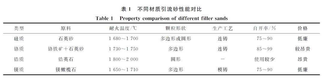
At present, the filler sand used at home and abroad mainly includes siliceous, chromium, zirconium and magnesium.
Silica filler sand is made from quartz sand as raw material and mixed with some additives such as alkaline feldspar. Silica filler sand is inexpensive, offers strong resistance to molten steel penetration, and boasts a high automatic pouring rate. It is widely used, currently accounting for approximately 20% to 30% of ladle drain sand. However, siliceous filler sand experiences significant volume expansion at high temperatures, resulting in reduced fluidity. Its acidic nature also shortens the life of the tundish.
Chromium filler sand, primarily made from chromite and quartz sand, boasts high density, a high melting point, excellent fluidity, and high refractoriness. It offers strong resistance to molten steel penetration and can maintain a high automatic pouring rate even after prolonged contact with molten steel. Currently, chromium filler sand is widely used by most steel mills, accounting for approximately 50% of all ladle drain sand.
Zirconium filler sand, primarily made from zircon, has rounded particles and boasts low thermal expansion, good thermal conductivity, high density, strong resistance to molten steel penetration, and excellent stability. It has long been considered an ideal ladle drain sand material. However, due to its high price, zirconium filler sand is rarely used on-site.
Magnesium filler sand is relatively inexpensive and is often used in die casting processes. Made primarily of forsterite, this type of filler sand exhibits high melting points, low thermal conductivity, minimal phase change expansion, stable chemical properties, and strong resistance to metal oxide corrosion. This type of filler sand has a low automatic pouring rate in continuous casting, with steel mills currently using only 15% to 20% of it. A comparison of the performance of four types of filler sand is shown in Table 1.
1.3 filler sand Sintering Structure
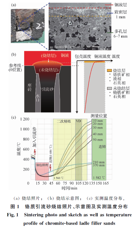
Rodcon et al. proposed that filler sand sintering exhibits a two-layer structure: the first layer is the sintered layer; the second layer is the original filler sand. Garlick C et al. found that drainage sands of different materials exhibit similar three-layer sintering structures: the top layer is the sintered layer, which is in direct contact with the molten steel and possesses a certain strength and thickness; the middle layer is the semi-sintered layer (partially sintered); and the bottom layer is the low-temperature zone, consisting of a loose layer similar to that at room temperature. The main difference in sintering between different filler sand materials lies in the relative thickness of each layer.
In reality, the thermal conductivity of filler sand is low, and its temperature drops rapidly with increasing distance from the molten steel. Therefore, the sintered layer of filler sand (including some of the sintered layer) is very thin, and the vast majority of the filler sand remains unsintered. Figure 1 shows a photograph, schematic diagram, and industrially measured temperature distribution of chromium filler sand during sintering. As shown in Figure 1, the sintered layer in contact with the molten steel is very dense, with a thickness of only about 1 mm. Below this thickness, the sintered layer begins to show a significant number of pores. Furthermore, as shown in Figure 1(c), the measured temperature of the filler sand near the ladle base bricks is already below 1200°C, making it difficult for the filler sand to sinter at this temperature. Therefore, achieving a reasonable sintered layer thickness is key to achieving automatic ladle pouring.
Previous Page:
Next Page:
Feedback
Leave a message now, and we will arrange for a specialist to contact you as soon as possible.
HENAN SINO INDUSTRIAL REFRACTORY NEW MATERIAL CO. LTD
Factory Address:
Mazhai, Zhengzhou, China
Nanlou, Dashiqiao, China
Xinmi, Zhengzhou, China
Samut Sakhon, Thailand
Klang ,Malaysia


Copyright © Henan Sino Industrial Refractory New Material Co. Ltd
Privacy Agreement Supports IPV6 SEO